DC Motor Torque, Speed, and Power Output
The purpose of a rotary DC motor is to deliver a desired rotational output speed while generating sufficient torque to overcome opposing rotational loads. These loads may include friction, inertia, external mechanical resistances, or operational demands like driving gears, belts, or connected machinery. The speed, torque and output power of a motor are directly related and play a pivotal role in assessing its suitability for specific applications.
Power (P) = Speed (n) x Torque (M)
- The mechanical output power of a motor is defined as the output speed times the output torque and is typically measured in Watts (W) or horsepower (hp).
Speed
- The speed of a motor is defined as the rate at which the motor rotates. The speed of an electric motor is measured in revolutions per minute, RPM.
Torque
- The torque output of a motor is the amount of rotational force that the motor develops. The torque of a small electric motor is commonly measured in either inch pounds (in-lbs), Newton meters (N-m) or other directly converted units of measure.
Since the rated output power of a motor is a fixed value, speed and torque share an inverse relationship: as the output torque increases, the output speed decreases proportionately. This fundamental relationship is commonly represented through a motor performance curve, which provides a detailed view of the motor's operational characteristics, including parameters such as motor current draw (Amps) and motor efficiency (%).
The balance and interplay of these factors are essential in ensuring the motor meets the performance requirements of a given application, whether it involves driving mechanical systems, delivering precise motion control, or operating under varying load conditions.
Consideration for Electric Motor Selection - Speed & Torque

Electric Motors Transform Electrical Energy Into Mechanical Energy
This process begins with an electric current flowing though copper wire coil windings wrapped around an iron core (stator), creating an electro-magnetic field that either opposes or attracts the magnetic field provided by permanent magnets moundted to a drive shaft (rotor). The interaction of the electromagnetic field with the permanent magnet field is what produces torque.
The motor's torque is influenced by several factors such as applied voltage, wire material and density, the number of coils, and the number of windings within each coil, which collectively define the electromagnetic field's strength, directly affecting the motor's ability to produce torque.
The maximum speed of the motor , on the other hand, is primarily determined by the amount of current flowing through the coils, as it dictates the rate at which the electromagnetic forces can drive the rotor. Consequently, the specific requirement of the application, such as torque and speed, play a critical role in defining the coil winding specifications, ensuring the motor perfmorms efficiently.
Torque and speed requirement change within the application
Since a motors torque and speed requirements vary across its application, it is critical to define all operating points. By calculating the speed and torque requirements at each operational point - such as startup, steady-state operation, acceleration, deceleration, and overload conditions, one can determine the overall speed and torque specifications needed to select the most suitable motor.
In many cases, application requirements necessitate selecting a standard motor that is significantly oversized to ensure that all operational points are covered. However, using an oversized motor often leads to unnecessary costs, as well as larger, heavier, and less efficient overall product designs.
Custom motors can be developed with optimized performance curves to precisely meet application requirements. This is done by changing the electromagnetic characteristics of the motor by altering either the wire size or the number of wire turns in the winding, or both. More turns of smaller wire provides more torque and less speed where fewer turns of larger wire provides higher speed but less torque. In some applications adding gearing to the motor output provides ideal speed versus torque relationship while keeping the cost and size of the overall solution to a minimum.
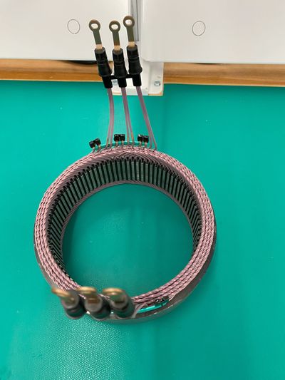
Stator Assembly & Design For Manufacturability (DFM)

Stator and Slots
- Number of slots: Depends on how many phases of power are provided to the coil windings. A basic three-phase motor usually has four slots that contain two pairs of coil windings, each pair offset by 120 degrees. Multiple of pole pairs can be utilized to increase the corresponding number of slots in the stator.
- Increased Magnetic Field Variation: By increasing the number of pole pairs, you create more alternating north and south magnetic poles around the circumference of the stator. This results in more points of magnetic interaction within the motor, which helps distribute magnetic flux more evenly and increases the precision of torque generation.
- Higher Slot Count: For each pole added, additional slots can be included in the stator to accommodate more windings. More slots allow for finer control of the magnetic fields and more options for winding arrangements. In turn, this can improve the motor's efficiency, reduce cogging torque, and allow for smoother operation at different speeds.
- Enhanced Winding Flexibility: With more slots available, there is more flexibility in designing the winding layout. This can enable distributed winding patterns, which are specifically useful in reducing harmonic distortion in the motor's magnetic field. Reducing harmonics leads to more efficient operation and reduced vibration noise.
Proper Machine Selection
- Optimized Power Density and Torque: By increasing the number of slots (via more pole pairs), you can optimize the torque per unit volume (power density) of the motor. This is particularly beneficial in applications where space is limited, such as in electric vehicles, where compact high-torque motors are desirable.
- Improved Efficiency at Higher Speeds: For motors intended to run at higher speeds, having more slots and pole pairs an help balance the forces acting on the rotor, reducing eddy current losses and minimizing core losses in the stator. This can result in more efficient motor for high-speed applications.
- Reduced Magnetic Flux Leakage: